|
|
|
![]()
KIT OF EQUIPMENT FOR DRAINAGE OF WELLS
![]()
|
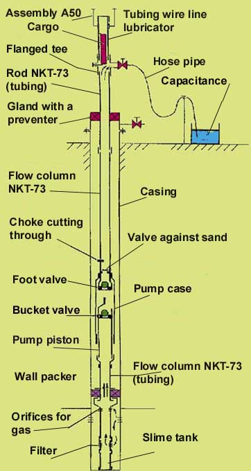
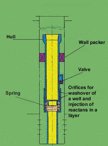
Bottom-hole the separator of a layer is intended for separation of a layer and well bore on time of production of any operations in a well requiring depressurization of its mouth (for example: substitution of the well pump, tubing descent and ascent, substitution of mouth armature and other). The separator contains the body with the central feed-through channel by a diameter of 58 mm (constantly opened for dipping under a wall packer of tubes, instruments, appliances and other equipment), wall packer, valve and orifices for washover of a well and pumping of reactants in a layer. The main effect from applying a separator is reached at the expense of canceling negative consequences caused by infiltration into a face zone of a layer during underground well repair of pressure fluid and her mechanical admixtures. As demonstrates the practice, the period of drop of productivity, after underground repair with mud lubrication, can be significant and durable In the cases row the productivity is not restored completely for period between-repairs of a well and there is an increasing decline of production of oil. |
 |
After the underground well repair equipped with a separator is completed, into first day of exploitation, takes place regeneration the preselected rate of yield. Not up to crude oil production, as it happens at mud lubrication of a layer, will not take place. The complementary crude oil production will be also at the expense of reduction of the period of idle time of a well because of time on pumping pressure fluid in a layer and pumpdown her from a layer. Will be cut down expenses for underground well repair because of the spent time on opening-up, transportation and pumping of service water (salt brine). Not busy assemblies for hauling and pumping of service water can be used on other assigning.
To essential dignity of separator is referred the opportunity to inject through him in a layer chemical reactants, resolvents and heat carriers, and also to effect washover of a sump of a well.
The wiring of separator in a well is dated to the next underground repair. Expediently after installing of separator to furbish a face zone of layer by drainage with the purpose of productivity recovery of a well worsened by the previous repairs with mud lubrication of a layer and during exploitation.
There is a kit of the engineering specifications on fabrication and exploitation of equipment.
The development is protected by the patents of Russian Federation for the inventions.
![]()
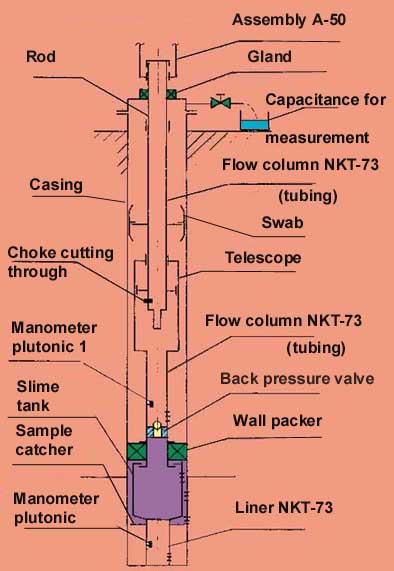 |
The swab for a casing allows to create repeated, short-term, regulable on magnitude (including, deep up to 0,8Р layer ) depression on a productive layer. It provides clearing a face zone of a layer from contaminating fragments and meliorating of fluid influx to a bottom hole. The integrated applying of a swab with bottom-hole by a separator of a layer, allows after clearing a face zone to effect change of downhole equipment and all subsequent well repairs without mud lubrication of a layer, i.e. without his repetitive impurity. The swab omit in well on the depth, applicable to chosen depression on a layer . Displacing a swab "hill up - downwards" periodically unload and load a layer by pressure of a fluid column which is taking place above a swab. By a difference in descent and ascent speed of a swab adjust a mode of flow of fluid in a face zone, and quality of its clearing. In case of use of a swab with a separator of a layer , his movement "hill up - downwards" calls only periodic discharging of a layer from pressure of a fluid column. By operation of a swab near to seam roof the below zero pulse of pressure can reach significant magnitude. Thus, the greatest possible effect from drainage of a well can be achieved at the expense of a complementary wave action on a layer.
|
CHARACTERISTICS.
Conventional diameter of a production casing, mm ................................................................................146
Diameter of the feed-through channel of a wall packer, mm .....................................................................58
The greatest difference of pressure perceived by a wall packer, Mpa....................................................... 5,0
Greatest temperature of an actuating medium, °C....................................................................................100
Load indispensable for removal of a wall packer, т, no more ................................................................. 2,0
External diameter at descent of a wall packer, mm ..................................................................................118
The guaranteed term of exploitation of a wall packer, years....................................................................... 5
Mass, kg ....................................................................................................................................................60
There is a kit of the engineering specifications on fabrication and exploitation of equipment.
The development is protected by the patents of Russian Federation for the inventions.
![]()
Copyright © firm "SPHERE". All rights reserved.
Revised: 05.15.99.